Basic Research- Technology
Instruments of Critical Path
By Michael J. Scianamblo, DDS, (Paul-Henri Valloton, PhD, and Gilbert Rota)
Instruments of Critical Path are a new set of endodontic instruments used to clean and enlarge the root canal space. Various prototypes that have been provided by Maiffeler International (Dentsply) are referred to nominally as X-Files or Swaggering Files. The “critical path” of the root canal space is defined as a path that is equidistant circumferentially from the center of the canal forming an ideal endodontic cavity preparation. A theoretical or “critical set” of instruments has been described, whereby the diameter of the files increase equally and is a function of the area of a circle πr^2 and, thereby, expands exponentially. The cutting edges or flutes are sharp and without radial lands. The instruments feature bi-symmetrical cross-sections that are off-set, placing the center of mass of the instrument at a specified distance away from the axis of rotation. The off-set center of mass allows the instruments to generate precession, and form mechanical waves within the canal. The instruments are, therefore, referred to as swaggering endodontic files. The swaggering effect attempts to enable the instrument to cut the inner and outer walls of a curvilinear space more evenly. In addition, the off-set design and concomitant precession, creates substantially wider clearance angles with improved hauling capacity. Wider cutting envelopes are also realized, allowing the operator to prepare the canal with fewer instruments, while minimizing binding and the predisposition to cyclic fatigue. Finally the instruments exhibit compressibility, which allows for safer cutting and greater facility in traversing complex bends.
Introduction
Walia (1988) was the first experimenter to discuss the use of nickel-titanium rotary instruments in endodontics and Wollcot (1997) demonstrated the substantial differential in resistance to torsional and flexural failure between stainless steel and Nickel Titanium. Glosson et al (1995), Esposito et al (1995), and Schafer and Florek (2003) have all suggested that Nickel-Titanium rotary instruments were superior to hand instrumentation in maintaining the original anatomy. Kum et al (2000), Gamberini (2001) and Calberson et al (2002), however, stated that the greatest failing of Nickel-Titanium designs is the continued predisposition to torsional and flexural fatigue.
Endodontic instruments of nickel-titanium can be found in a myriad of shapes and sizes. They are ground or cut from nickel-titanium blanks. In cross-section, the earliest designs were instruments with two cutting surfaces (McSpadden, 1982 and 1984 and Arpaio, 1985 and 1986), which displayed “positive” rake angles (Figure 1A and B). The notion of a positive rakes angles, however, was disputed by Chow et al (2005).


The cutting efficiency of an endodontic instrument does depend on the design and configuration of the rake angle. Instruments with negative rake angles require more energy to cut dentin than instruments with a neutral or positive rake angles and are, therefore, less efficient (Wildey et al, 1992). Arpaio and Heath (1989 and 1990) introduced an instrument with a triple helix or three cutting surfaces displaying radial lands, negative cutting angles and a U-shaped cross-section (Figure 2). In transverse cross-section, the instruments mimic the G-type or Gates-Glidden drill. The prominent lands were deemed to provide enough “drag” on the file to prevent binding and breakage. These instruments were further discussed by Buchanan (1989) and Johnson (2000) and nominally referred as Profiles. The value of radial land remains was debated in Endodontic: Colleagues foe Excellence (2008). Turpin et al (2000 and 2001) has demonstrated that the focus of torsional stress is in the deepest portion of the flutes, which is logical since breakage always occurs in narrowest cross-section of the web. Thus, U-files have low cross-sectional mass and low torsionsal inertia and may be more predisposed to torsional failure.
McSpadden (1998 and 1999) discussed the use of asymmetric cores, in combination with positive cutting angles, and recessed radial lands adjacent to the flutes. An instrument that is marketed by Kerr-Sybron as an asymmetrical file with a triple helix and radial lands and lands reliefs is known is the K-3 file. The flute design is comparable that of a twist drill (Kallio 1960 and Kim 1980).
All the instruments described above are designed with right-handed cut and right-handed helix (Figure 1A and B). Thus, they can act like a screw. The nature of these designs can allow the instruments to bind in the canals, also referred to as taper lock, which predispose the instruments to cyclic fatigue and breakage (Yao 2006).
Numerous investigators have tried to mitigate these problems. The variable taper system described by Maiffler (1997 and 1998), called the Protaper, does mitigate some of the problem of binding, however, Cheung (2005) and Spanaki-Voredi et al (2006) demonstrated that these instruments were still subject to flexural failure and spontaneous fracture. Remarkably, many investigators could not find a statistically significant difference between the effectiveness of any one instrument over another (Kum, et al, 2000, Peters, et al, 2001, and Ahlquist, et al, 2001).
Heretofore, all endodontic instrument designs have a center of rotation and a center of mass that are identical, dictating a linear trajectory and path of motion. These designs, of course, facilitate elastic memory and the restoration of their original shape. The application of nickel-titanium in the manufacture of endodontic files, further facilitates this function. This has been thought to be of paramount importance during root canal preparation, however, the work of Peters et al (2001) has indicated that it is this precise function, that prevents the instruments from contacting the entire anatomy of the root canal preparation, leaving as much as 35% of the internal anatomy of the canal untouched and the preparation poorly centered.
Instruments of Critical Path
Instruments of critical path represent a new concept in endodontic file design in which the center of mass and the center of rotation are no longer coincident, but are intentionally off-set. The axis of rotation (central axis) of the X-file, which defines the theoretical center of rotation, is shown by axis 1 (Figure 3). Axis 2 follows the geometric center of the X-file. The amount of off-set between the center of rotation and the center of mass is defined by the distance between these two axes and varies along the length of the file (shown as the distance x in Figure 3)

Due to the offset center of mass, which is inherent in this design, the X-file experiences a phenomenon during rotation that is known as precession or swagger. Precession describes the motion which occurs whenever the axis about which a body is spinning is, itself, rotating about another axis. When observed during operation, precession of the file gives the appearance of a traveling wave. In addition to its unique appearance during operation, the waveform analogy provides a useful method for analyzing the function of the X-file (Scianamblo, 2005, 2006, 2011).
Precession, in general terms, describes the motion which occurs whenever the axis about which a body is spinning is, itself, rotating about another axis. The use of the term precession is often referred to when describing the motion of planetary bodies and is called perihelion or apsidal precession. The most common example of classical mechanical precession is the motion of a spinning top (figure 4).
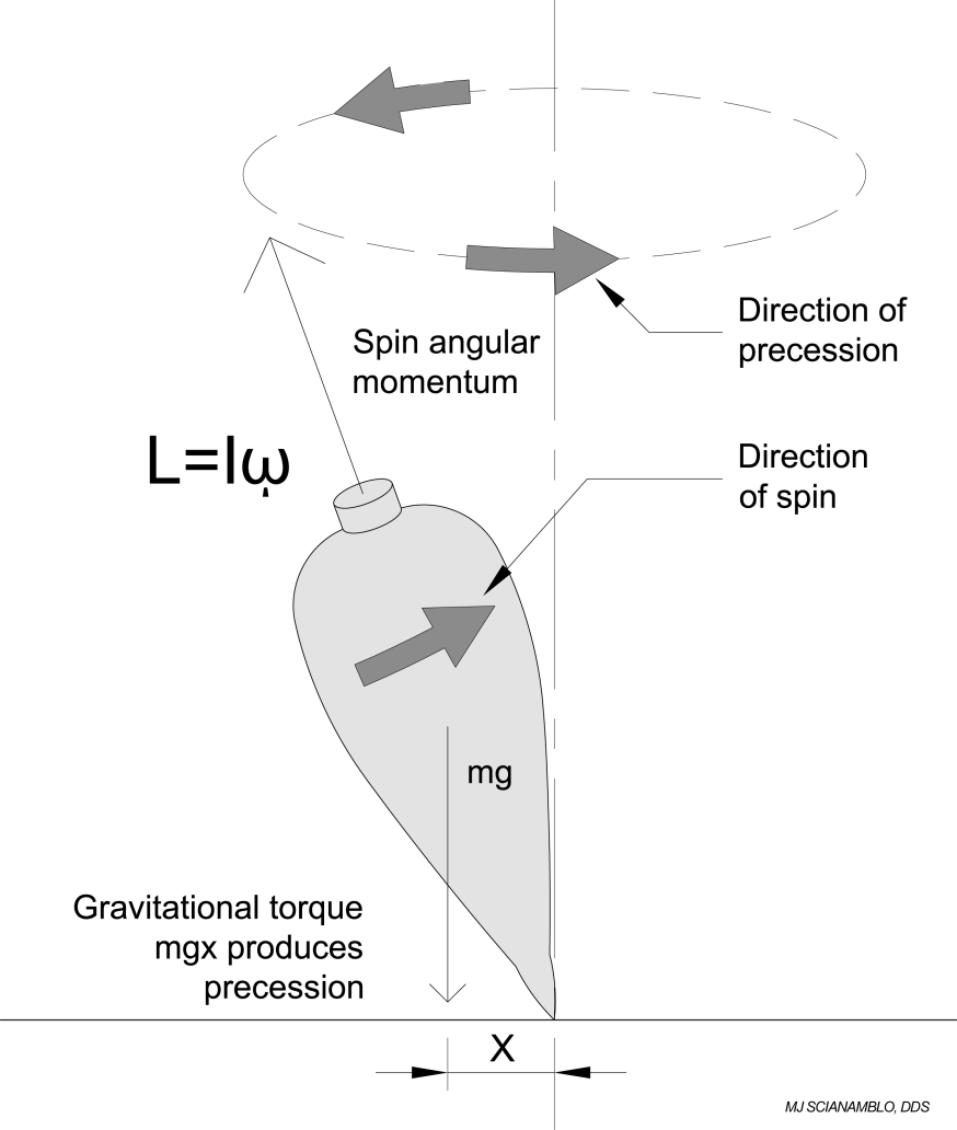
In its simplest terms, mechanical precession is the clearance that is created by the off-set motion of a round part rotating in a round hole of another part. Pictorialization of the rotational motion of the X-File (Figure 5), clearly shows segments or nodes of the file rotating about itself while at the same time rotating about a central axis. What differentiates the X-file from the example above is the method used to generate the axis of precession. In the case of the spinning top, the axis of precession is controlled by external variables, specifically gravitation pull. In the case of the X-files, the axis of precession is “inherent” or ground into design and not controlled by external variables. By building the axis of precession into the file, the precession angle, and therefore the cutting action, can be precisely controlled.
Theoretically, with adequate angular velocity and a sufficient off-set center of mass, the X-File could experience angular accelerations, which could in turn produce bodily movement. Regardless of the origin, the wave analogy provides a good method for describing the file geometry.
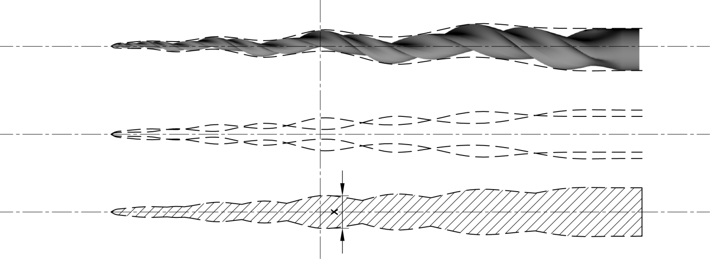
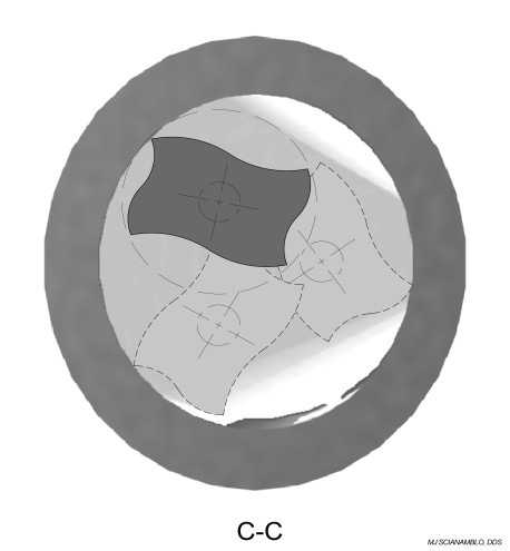
For further analysis, we will define each arc as a wave of amplitude x as shown in Figure 5. The total distance traveled by any point on the arc, then, equals 2x, which defines the cut diameter. Thus, the cutting envelope associated with any node along the instrument’s profile is twice as wide as the instrument at that cross-section.
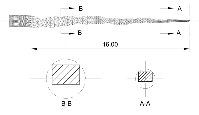
The file design, shown in Figure 6 (below), is now being introduced and referred to as an ProTaper Next. As previously mentioned, the off-set rectilinear cross-section cuts intermittently. As can be seen from this figure, only two cutting angles engage the walls of the root canal at any one time. The combination of these features allows the instrument to create larger cutting envelopes with a smaller cross-sectional area compared to previous designs. This improves flexibility, improves resistance cyclic fatigue, mitigates binding or taper lock (the screwing effect), and mitigates transportation of the canal, which will be demonstrated in the mechanical analysis below.
Torque resistance
Method
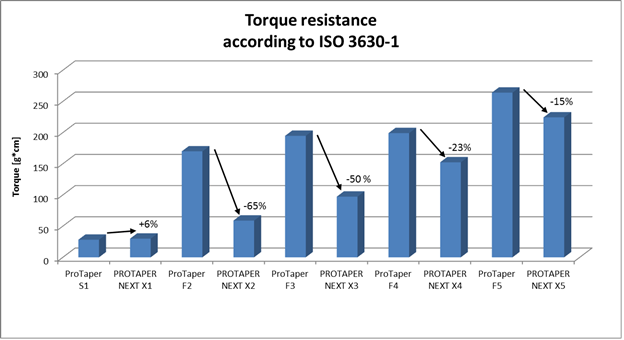
Ten sets of the X-files (ProTaper Next) and ten sets the F- files (ProTaper Universal) were tested. Each set included five files: for ProTaper Next sizes 17/04, 25/06, 30/07, 40/06 and 50/06 and for ProTaper Universal sizes 20/07, 25/08, 30/09, 40/06 and 50/05. The measurement of the torque until breakage was performed according to the ISO 3630-1 specifications. The instrument was fixed at 3mm from the tip and rotated at 2 rpm until fracture occurred.
Sampling: 10 instruments of each size manufactured from three different raw material lots.
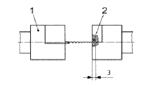
2) Fixing parts made in brass
Results
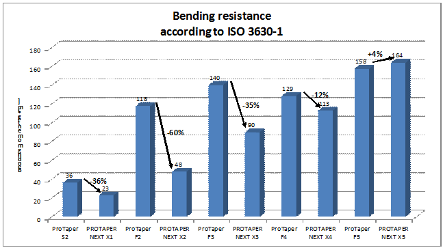
Bending Resistance
Method
Ten sets of the X-files (ProTaper Next) and ten sets the F- files (ProTaper Universal) were tested. Each set included five files: for ProTaper Next sizes 17/04, 25/06, 30/07, 40/06 and 50/06 and for ProTaper Universal sizes 20/07, 25/08, 30/09, 40/06 and 50/05. The measurement of the bending moment was performed according to the ISO 3630-1 specifications. The instrument was fixed at 3mm from the tip, bent perpendicularly to the instrument axis until 45° and then bent back to its initial position.
Sampling: 10 instruments of each size manufactured from three different raw material lots
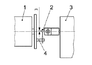
2) Stop
3) Torque sensor
4) Drive part
Results
Cyclic Fatigue Test
Method
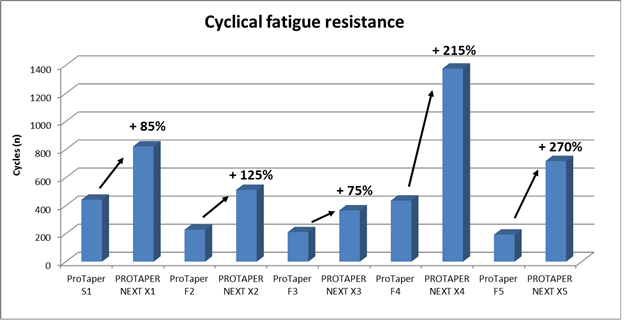
Ten sets of the X-files (ProTaper Next) and ten sets the F- files (ProTaper Universal) were tested. Each set included five files: for ProTaper Next sizes 17/04, 25/06, 30/07, 40/06 and 50/06 and for ProTaper Universal sizes 20/07, 25/08, 30/09, 40/06 and 50/05. A specific bench was developed by MAILLEFER to test the cyclical fatigue. A 5mm radius curvature was used to test the PROTAPER NEXTTM X1 to X3 whereas we used a 10mm radius curvature for PROTAPER NEXTTM X4 and X5. An air cooling spray (2 bar) at ambient temperature was used to avoid the heat of the instrument. A rotation speed of 300rpm was used. Sampling: 10 instruments of each size manufactured from three different raw material lots
Results
Screwing effect
Method
Five sets of the X-files (ProTaper Next) and five sets the F- files (ProTaper Universal) were tested. Each set included five files: for ProTaper Next sizes 17/04, 25/06, 30/07, 40/06 and 50/06 and for ProTaper Universal sizes 20/07, 25/08, 30/09, 40/06 and 50/05. The test was performed on a specific bench able to measure the force (Newton) during the test made in plastic blocks. The goal was to compare the screwing effect between ProTaper Universal versus PROTAPER NEXTTM.
5 instruments of each type were used in Endo-Training-Blocs with straight canal (Ref A0177) without any previous preparation. The following settings were used for both instruments:
1) Forward speed: 0.3mm/s
2) Rotation speed of 350rpm
3) Torque control to 2cN.m.
Sampling : 5 blocs per instrument size
Results
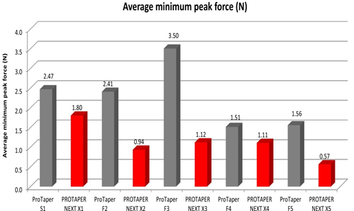
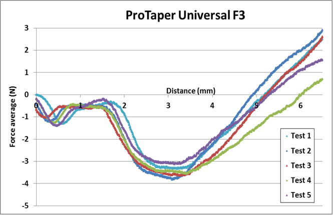
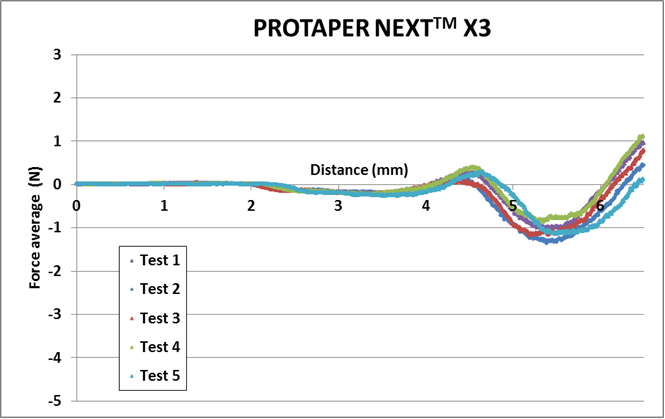
On the following graphs, when the force is negative that means we observed a screwing effect; when the force is positive that means we have to push the instrument; ideally when the force is to a 0 value, the instrument is perceived as neutral meaning no screwing effect and no pushing action to move forward into the root canal. The charts (below) for the F3 and X3 are representative of all the test for X1-X5 and S1-F5.
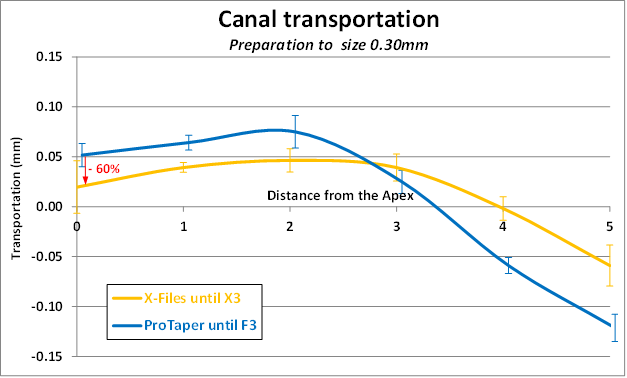
Root Canal Transportation
Method
Five sets of the X-files (ProTaper Next) and five sets the F- files (ProTaper Universal) were tested. Each set included five files: for ProTaper Next sizes 17/04, 25/06, 30/07, 40/06 and 50/06 and for ProTaper Universal sizes 20/07, 25/08, 30/09, 40/06 and 50/05. The root canal transportation was performed in plastic blocks Ref A0177 / Ø 0.15mm) having a simple curved root canal. The procedure used to measure the transportation was to superpose the initial root canal shape with the one we obtained after instrumentation. Measurements were made after each instrument size using the complete sequence for both systems that were ProTaper Universal & PROTAPER NEXTTM. Sampling : 5 blocs per instrument type
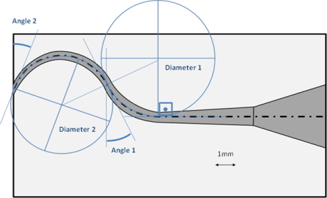
Question for Maillefer: It is unclear whether this of another model was used to evaluate Transportation. If another model was used, can you provide a detailed diagram?
Results
The charts (below) for the F3 and X3 are representative of all the test for X1-X5 and S1-F5.
Discussion
Analysis of the File as a Variable Rate Spring
The majority of these improvements exhibited by the X-File are not only a function of the off-set design and intermittent cutting action, but is a function of its flexibility and it’s unique coil or spring-like characteristics. Stiffness and/or flexibility, is often referred to as a spring constant, and is defined as the amount of force that is required to cause a unit of deformation. In its general form, k = F / δ, where k equals the stiffness, F equals force and δ equals displacement. Equations for the determination of the spring constant of actual mechanical systems are widely available in engineering literature. Due to the constantly changing cross section of the X-File, the spring constant of the file will vary along its length. This spring constant, together with the file precession described in the introduction, directly affect the cutting forces applied to the surrounding material during application.
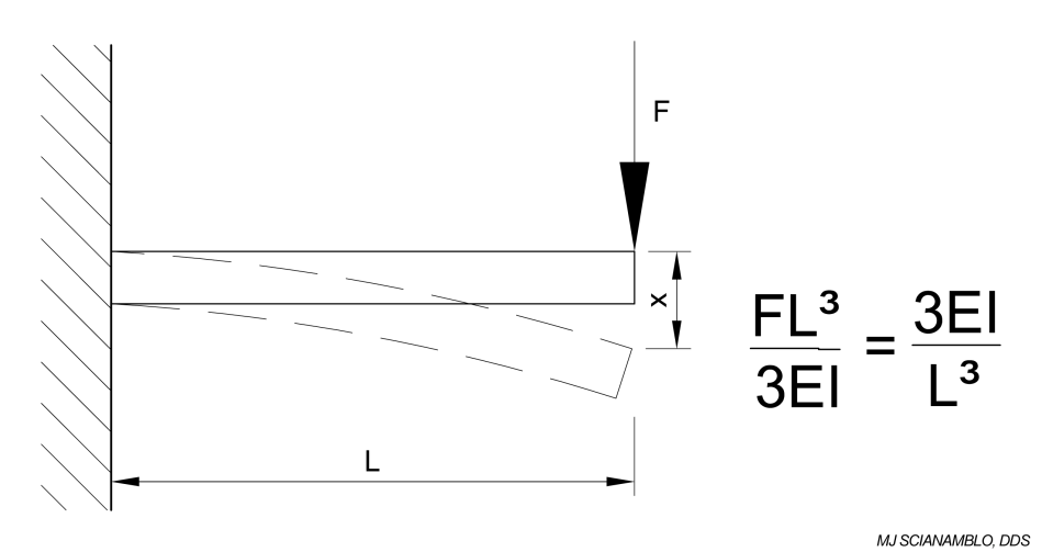
In the first part of this analysis, we look at the spring condition along the entire length of the file. There are two configurations that are possible when considering designs with an off-set center of mass: 1. Off-set is at the shank (with the tip centered) or 2. Off-set is at the tip (with the shank centered) reversing the direction of the off-set angle, as shown in Figure 7A. The following discussion is applicable to both the off-set shank and the off-set tip designs.
Similar to a Cantilever Beam
A file with off-set design in its unconstrained condition is shown in Figure 7A. If this file is inserted into a relatively straight cavity with a diameter that is close to the diameter of the file, the file will be constrained along its length such that axis of rotation and the central axis are aligned. The resulting condition can be analyzed in general terms using the equation for a cantilever beam in Figure 7B. As the file is rotated, it will naturally want to precess and try to return to its unconstrained position, which will be dependent upon its stiffness, k.

Max Deflection (x), Stiffness (k)
Similar to a Supported Beam
In a second analysis, we look at a localized section of the file as it is bent to conform to the cavity during use, shown as L in Figure 8A. If we define the localized section of the file to be analyzed using the terminology defined in the waveform discussion above, we can analyze the spring rate of a single wave crest between two nodes. In this application the stiffness can be analyzed using the equations for a simply supported beam (Figure 8B).

Max Deflection (x) Stiffness (k)
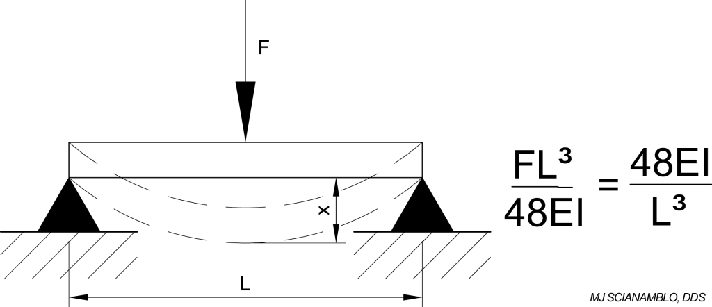
We define the variables presented in figures 8A and 8B with respect to the X-File as follows: L would represent the distance between any two nodes. I represents the moment of inertia which is dependent upon the cross sectional area of the file and will vary along its length. E represents the modulus of elasticity (Young’s Modulus) which is used to define the stiffness of different materials.
Evaluating the initial conditions of the X-file as it is inserted into a root canal space, we look at the reverse of what is depicted in figures 7A and 8A above. The X-File is built with a deflection in its unconstrained condition. The maximum deflection in the unconstrained condition of the off-set tip design is at the tip of the file and the maximum deflection of the off-set shank design is at the base of the shank. F represents the force exerted on the file by the cavity wall. Since the X-file is built with a natural deflection, the tendency of F will be to straighten out the file along its length. When the file is fully constrained, x, which represents the deflection of the file due to F would initially be zero (or nearly zero). The calculations as presented in figures 7B and 8B also apply to this reverse condition and are applicable here. As the file begins to rotate, its tendency will be to return to the natural state in which it is precessing about its central axis. As it attempts to precess, the cutting edges, under the load of the spring force, will begin to remove material from the surrounding cavity. This process will continue until the file has created an enlarged cavity based the file diameter and the precession axis. In this final unconstrained condition, the spring force (cutting force) will be nearly zero and the file will be rotating freely about the central axis.
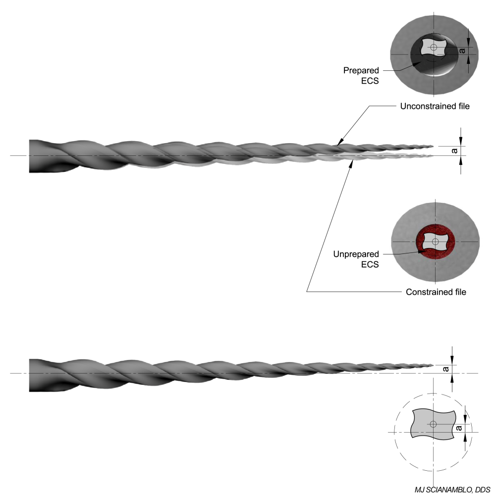
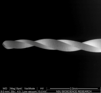
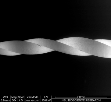
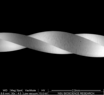
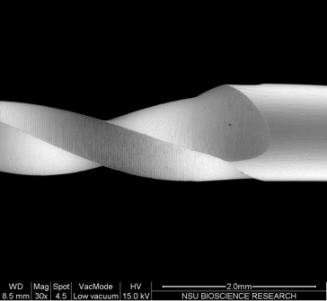
In application, this condition allows the file to be designed to maximize the cutting forces between specific nodes and at the same time reduce the spring force at the tip. The cutting envelope that occurs between nodes is depicted in Figure 9. Figures 10A -10D are scanning electron micrograph of the instrument itself.
Figures 10A, 10B, 10C and 10D S. KUTLER, DDS
 |
 |
 |
 |
|
10A |
10B |
10C |
10D |
In the center section image in Figure 9, the cross section of the file is shown during initial insertion of the file into the cavity. In this condition, the cavity is constraining the file, such that the axis of rotation is nearly aligned with the central axis. In both the top and the bottom section views in Figure 9, the position of the file is shown after sufficient rotation to return to its unconstrained position. The ability of the file to cycle back and forth between its constrained and unconstrained condition is dependent upon both the file geometry and the material properties.
If we evaluate a “wire perspective” of the X-File (Figure 11A) and a scanning electron microscopic image (Figure 11B) of the profile, a spring or coil-like becomes more evident.
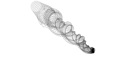
Figure 11A
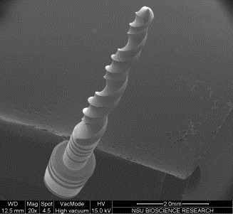
Figure 11B
A design of this nature, would allow the instrument to engage the root canal space intermittently as the constrained coil is inserted in the canal and allowed to unwind (Figure 12.1-12.3) releasing a theoretical amount of stored energy. This would be of benefit in reducing the operating pressure or torque used to engage the instrument minimizing binding and cyclic fatigue, while improving the opportunity to clean both inner and outer walls of the canal more thoroughly.
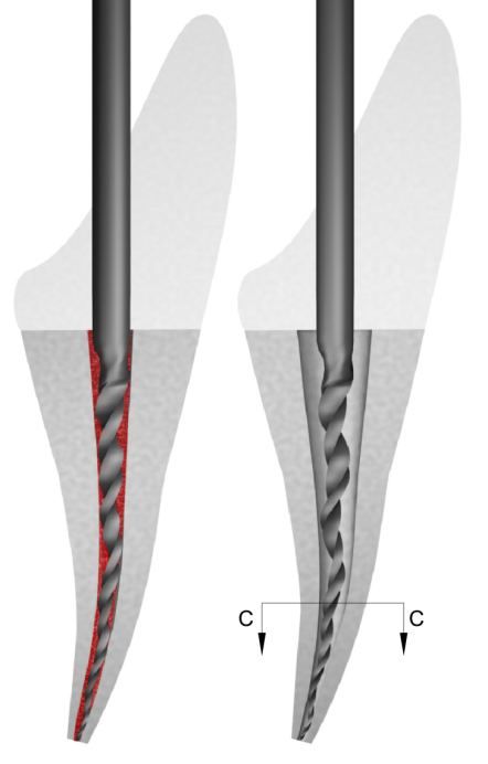
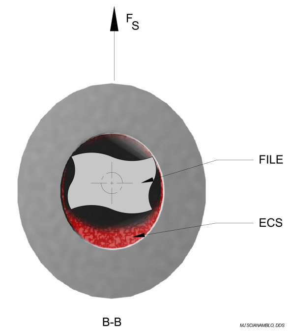
An additional benefit of any instrument that displays the attributes of a variable spring is compressibility, which will be discussed in the next section
Conclusions
The technical analysis of the X-File has defined the rotating motion of the file as a form of precession. When observed, the precessing motion of the file appears as a traveling wave. This undulation motion, in combination with improved flexibility and spring-like characteristics, appears to provide a new generation of endodontic instruments with superior operating capabilities.
References
Ahlquist, M, Henningsson, O, Hultenby, K, and Ohlin, J: The effectiveness of manual and rotary techniques in the cleaning of root canals: a scanning electron microscopy study. Int Endo J, 34:533-537, 2001
Arpaio, J. An endodontic instrument. U.S. Patent No. 4,538,989, Sept, 1985.
Berutti, E: Computerized analysis of the instrumentation of the root canal system. Second Endodontic World Congress. Paris, France, June, 1992
Buchanan, LS: Anti-curvature dental root canal shaping file. U.S. Patent No. 4,836,780. June, 1989
Calberson, FL, Deroose, AJ, Hommez, GM, and DeMoor, RJ: Shaping ability of GT Rotary Files in simulated resin root canals. Int J Endod 35:607-614, 2002
Cheung GS et al: Defects in ProTaper S1 instruments after clinical use. Int Endod J. 38:802-9, 2005
Chow D, Stover, SE, Bachal, JK, Jaunberzins, A and Toth, JM. An in vitro comparison of the rake angles between K3 and ProFile endodontic file systems. J Endod 31:180-182, 2005
Endodontics: Colleagues for Excellence, Rotary Instrumentation: An Endodontic Perspective, Pgs. 1-5, Winter 2008
Esposito, PT and Cunningham, CJ: a comparison of canal preparations with nickel-titanium and stainless steel instruments. J Endod 21:173-176, 1995
Gambarini, G: Cyclic fatigue of Profile rotary instruments after prolonged clinical use. Int Endo J, 34:386-389, 2001
Glosson, CR, Haller, RH, Dove, SB, and Del Rio, CE: A comparison of root canal preparations using N-Ti hand, Ni-Ti engine-driven and K-flex endodontic instruments. J Endod, 21:146-151
Heath, DE. Endodontic instrument. U.S. Patent No. 4,871,312, Oct, 1989
Hulsman, M, and Stryga, F: Comparison of root canal preparations using different automated devices and hand instrumentation. J Endod 19:141-145, 1993
Gambarini, G: Cyclic fatigue of Profile rotary instruments after prolonged clinical use. Int Endo J, 34:386-389, 2001
Johnson, WB: Method of endodontic preparation of a root canal and a file set for use in the method, 6106296, August 2000
Kallio, WJ: Industrial Twist Drill. U.S. Patent No. 2,966,081 Dec. 1960
Kim, JB: Twist drill. U.S. Patent No. 4,209,275. June, 1980.
Kum, KY, Spängberg, L, Bruce, YC, Jung, IY, Seung-Jong, L and Chan-Young, L. Shaping ability of three Profile rotary instrumentation techniques in simulated resin root canals. J. Endod 26:719-723, 2000
McSpadden, J.: U.S. Patent No. 4,332,561, June 1, 1982
McSpadden, JT: Endodontic instrument. U.S. Patent No. 4,457,710, July, 1984
McSpadden, JT: Endodontic instrument. U.S. Patent No. 5,735,689, April,1998
McSpadden, JT: Endodontic instrument. U.S. Patent No. 5,902,106, May, 1999.
Maillefer, PL and Aeby, F: Instrument for boring dental radicular canals. US Patent No. 5,746,597, May, 1998
Peters, OA, Schonenberger, K and Laib, A: Effects of four Ni-Ti preparation techniques on root canal geometry assessed by micro computed tomography. Int Endo J, 34:221-230, 2001
Roane JB, Sabala CL, and Duncanson MG Jr: The “balanced force” concept for instrumentation of curved canals. J Endod 11:203, 1985
Scianamblo, MJ. Critical path endodontic instruments for preparing endodontic cavity spaces. U.S. Patent No. 6,942,484, Sept, 2005
Scianamblo, MJ. Endodontic instruments for preparing endodontic cavity spaces. U.S. Patent No. 7,955,078, June, 2011
Scianamblo, MJ. Critical path endodontic instruments for preparing endodontic cavity spaces. U.S. Patent No. 6,942,484, Sept, 1
Scianamblo, MJ. Critical path endodontic instruments for preparing endodontic cavity spaces. U.S. Patent No. 20060228669 Oct. 2006
Scianamblo, MJ. Bending endodontic instruments. EPO Patent No. 1,709,934 B1 Apr. 2006
Spanaki-Voredi AP, Kerezoudis NP, Zinelis S: Failure mechanism of ProTaper Ni-Ti rotary instruments during clinical use: fractographic analysis. Int Endod J. 39:171-8, 2006
Schäfer, E. and Florek, H, Efficiency of rotary Nickel-titanium K3 instruments compared with stainless steel hand K-Flexofile. Part 1. Shaping ability in simulated curved canals. Int Endo J 36:199-207, 2003
Schilder H: Cleaning and shaping the root canal. Dent Clin North Am 18:269, 1974
Turpin, Y, Chagneau, F, and Vulcan, J: Impact of two theoretical cross-sections on torsional and bending stresses of nickel-titanium root canal instrument models. J Endod 26:414-417, 2000
Turpin, Y, Chagneau, F, Bartier, O, Catheineau, G and Vulcan, J: Impact of torsional and bending inertia on root canal instruments. J Endod 27:333-336, 2001
Walia, H, Brantley, WA, and Gerstein, H: An initial investigation of the bending and torsional properties of nitinol root canal files. J Endod, 14:346-351, 1988
Weine FS, Kelly RF, and Lio PI: The effect of preparation procedures on original canal shape and on apical formation shape. J Endod 1:255, 1975
Wildey, WI, Senia, S, and Montgomery, S: Another look at root canal instrumentation. Oral Surgery, 74:499-507, 1992
Wolcott, J. and Himel, V., ” Torsional Properties of Nickel-Titanium versus Stainless Steel Endodontic Files.” JOE 1997; 23:4:217
Yao JH, Schwartz SA, Beeson TJ. Cyclic fatigue of three types of rotary nickel-titanium files in a dynamic model. J Endod;32:55–57, 2006
Publication pending. All rights are reserved by Critical Path Technology. The contents of this article may not be reproduced, downloaded, disseminated, published, or transferred in any form or by any means, except with the prior written permission.
